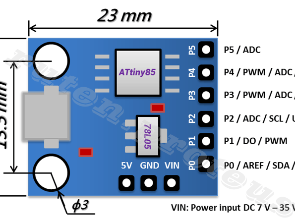
Se vuoi spendere poco ed avere un buon funzionamento, usa dei Attiny85.
Qui un esempio di funzionamento
https://www.youtube.com/watch?time_continue=2&v=T1ixxKuPiYg&feature=emb_logoQui lo sketch da caricare con la suite di arduino
int decoderAddress = 15; // This is the decoder address.
#define F1_pin 3 // Available pin numbers: 0,1,3,4,5
#define F2_pin 4
#include <DCC_Decoder.h>
#define kDCC_INTERRUPT 0
byte Func[4]; //0=L4321, 1=8765, 2=CBA9, 3=F20-F13, 4=F28-F21
byte instrByte1;
int Address;
byte forw_rev=1; //0=reverse, 1=forward
boolean RawPacket_Handler(byte pktByteCount, byte* dccPacket) {
Address=0;
if (!bitRead(dccPacket[0],7)) { //bit7=0 -> Loc Decoder Short Address
Address = dccPacket[0];
instrByte1 = dccPacket[1];
}
else if (bitRead(dccPacket[0],6)) { //bit7=1 AND bit6=1 -> Loc Decoder Long Address
Address = 256 * (dccPacket[0] & B00000111) + dccPacket[1];
instrByte1 = dccPacket[2];
}
if (Address==decoderAddress) {
byte instructionType = instrByte1>>5;
switch (instructionType) {
case 2: // Reverse speed
forw_rev=0;
break;
case 3: // Forward speed
forw_rev=1;
break;
case 4: // Loc Function L-4-3-2-1
Func[0]=instrByte1&B00011111;
break;
case 5: // Loc Function 8-7-6-5
if (bitRead(instrByte1,4)) {
Func[1]=instrByte1&B00001111;
}
else { // Loc Function 12-11-10-9
Func[2]=instrByte1&B00001111;
}
break;
}
if (Func[0]&B00000001) digitalWrite(F1_pin,HIGH); else digitalWrite(F1_pin,LOW);
if (Func[0]&B00000010) digitalWrite(F2_pin,HIGH); else digitalWrite(F2_pin,LOW);
}
}
void setup() {
DCC.SetRawPacketHandler(RawPacket_Handler);
DCC.SetupMonitor( kDCC_INTERRUPT );
pinMode(0, OUTPUT);
pinMode(1, OUTPUT);
pinMode(3, OUTPUT);
pinMode(4, OUTPUT);
pinMode(5, OUTPUT);
}
void loop() {
DCC.loop();
}
Il tutto costa pochi spiccioli: 3-4 Eur; il decoder si comporta come un decoder da loco. Con F1 proietti luce verde, tramite F2 proietti luce rossa; lasciando entrambe le funzioni attive verrà proiettata luce gialla (entrambi i led accesi).